1. Introduction
Integrated Circuit (IC) reballing has become one of the most important repair techniques in modern computer and laptop repair services, enabling the speedy upgrading of the latest models. As devices grow smaller and more complex, the reliability of solder ball connections plays a critical role in ensuring stable performance. VGA-type I/O chips, in particular, are highly susceptible to solder fatigue due to constant thermal cycling, high-end data processing stress, and heavy workloads. When these connections fail, symptoms such as display-related problems, intermittent signals, Hang, freeze, sometimes keyboard not working, or complete device malfunction often appear.
Reballing offers a cost-effective alternative to full chip replacement, allowing technicians to restore functionality by renewing the solder ball grid beneath the IC. Among the various methods available, the direct heating stencil technique has gained popularity for its precision, efficiency, and reduced risk of misalignment. By applying controlled heat directly through a stencil, technicians can achieve consistent ball placement and strong adhesion, even on complex VGA-type I/O chips.
This blog will explore the tricks, tips, and technical knowledge behind ITE, ENE, Lenovo, and SIO IC reballing using direct heating stencils. Whether you’re a beginner learning the fundamentals or an experienced repair professional seeking advanced insight, the following sections will guide you through tools, processes, common mistakes, and expert techniques to master this critical repair skill.
Beginners can start from here:

2. Understanding VGA-Type I/O Chips
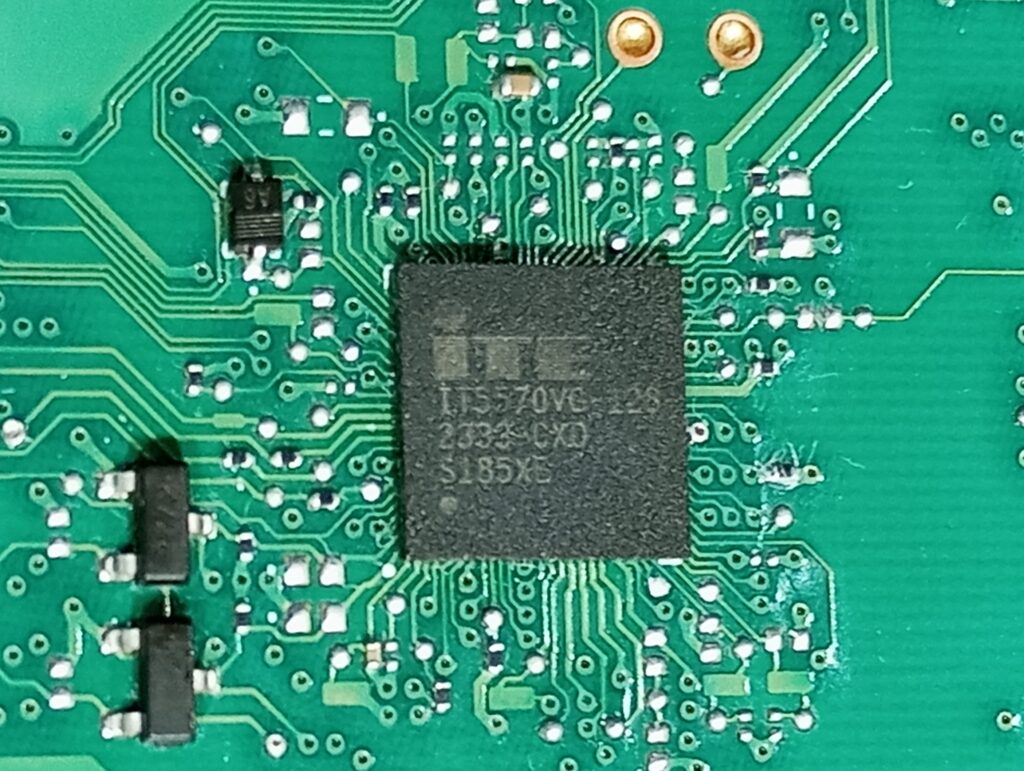
VGA-type I/O chips are specialized integrated circuits responsible for handling video graphics array signals and managing input/output operations between the CPU, PCH, or SoC chip, USB, power infrastructures, display, and the motherboard. These chips act as the bridge that translates digital instructions into visual output, making them critical for stable Digital performance in laptops, desktops, and other electronic devices.
Because of their role in high-frequency data transfer and Managed Power Infrastructures, VGA I/O chips are particularly vulnerable to solder joint fatigue. Over time, the microscopic solder balls beneath the chip can crack, oxidize, or lose adhesion, leading to intermittent or complete signal failure. This is why technicians often encounter issues such as:
• Distorted or flickering display output
• No video signal despite power-on
• Complete no power
• Keyboard and touchpad sometimes not working or permanently not working problems
• Overheating or unstable performance during graphics-intensive tasks
• Internal short circuits, etc.
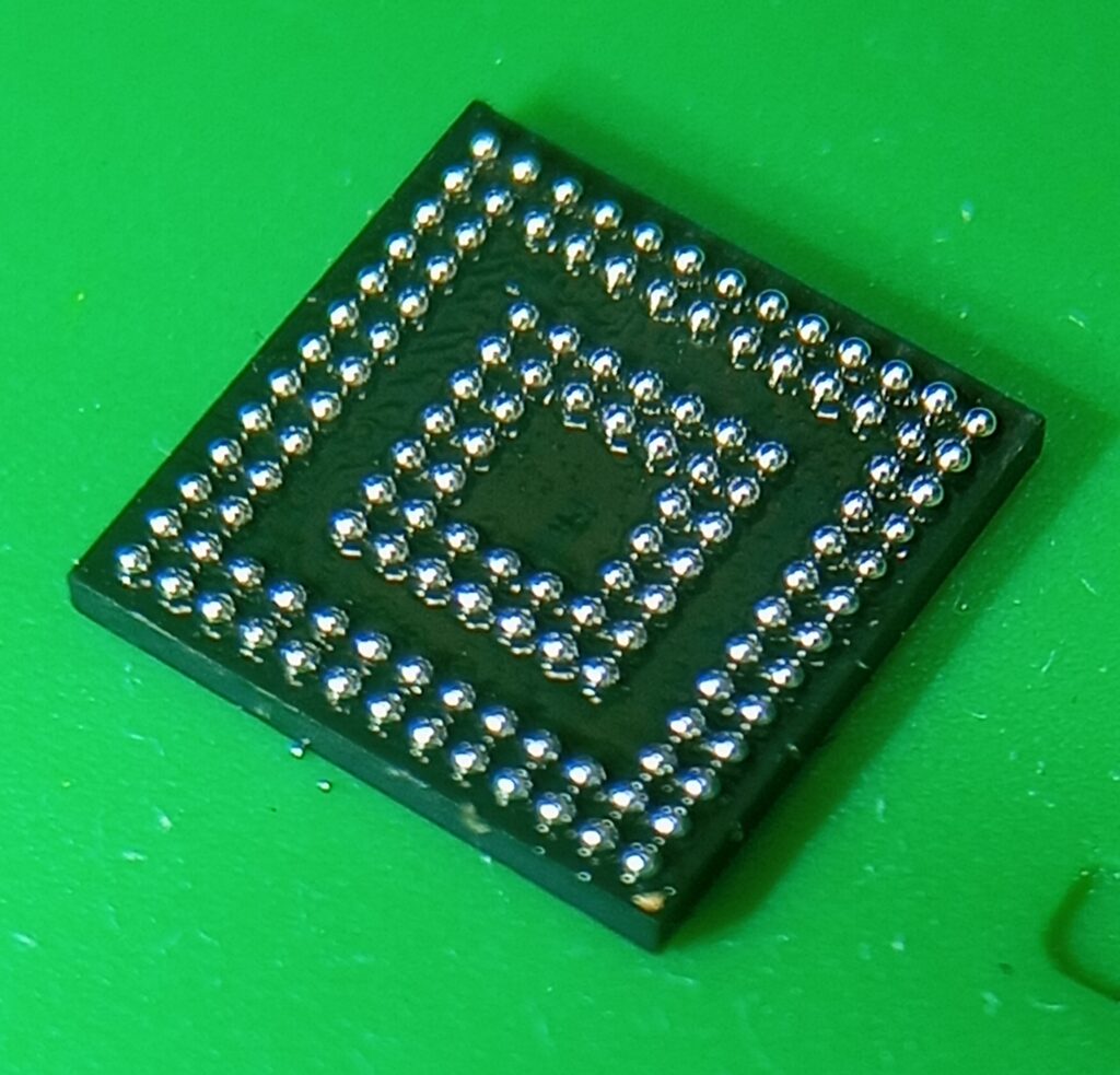
Reballing becomes necessary when these solder connections fail, but the chip itself remains functional. Instead of replacing the entire IC—which can be costly and sometimes difficult to source—reballing restores the chip’s connectivity by renewing the solder ball grid. For VGA-type I/O chips, this process is especially important because their fine-pitch ball layout demands precision and consistency to ensure reliable operation.
By understanding the structure and common failure modes of new models VGA I/O chips, technicians can better appreciate why reballing is such a vital repair skill. This knowledge sets the stage for exploring the tools and new technology, quick understanding ability, methods, and tricks that make direct heating stencil reballing both effective and efficient.
3. Tools & Materials Needed
Successful IC reballing, especially for VGA-type I/O chips, depends heavily on having the right tools and materials. Precision and consistency are key, and using substandard equipment can lead to poor results or even damage the chip. Below is a comprehensive list of what every technician should prepare before attempting the direct heating stencil method:
🔧 Essential Tools
Very Low Air Adjustable Hot Air Rework Station
Provides controlled airflow and temperature for melting solder balls evenly. Very low Adjustable air and heat profiles are critical to avoid accurate location and overheating the chip. And low air flow is very important for this type of IC due to its very light weight.
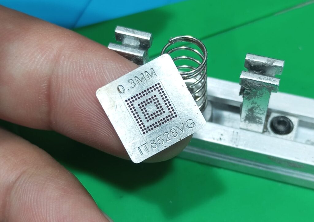
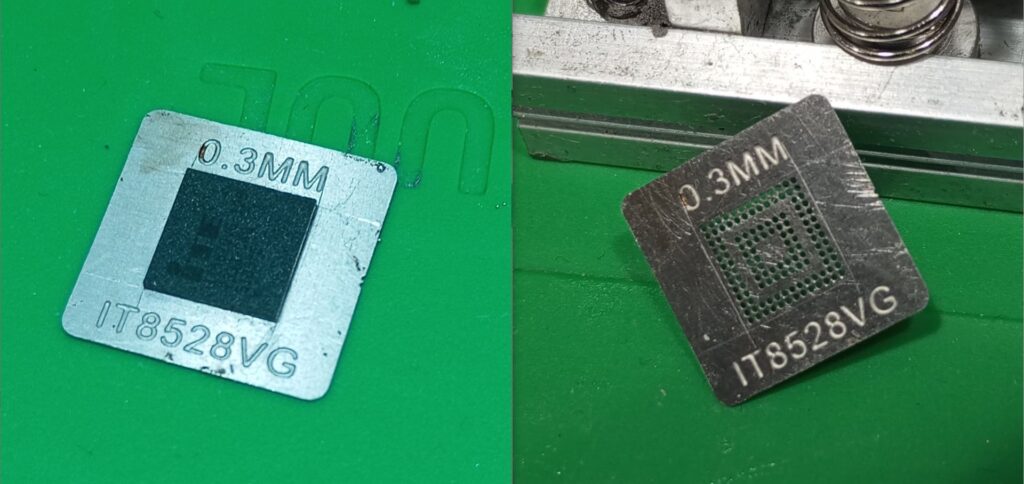
0.3 MM IT8528VG Direct Heating Stencils
Specially designed stencils that match the ball grid layout of VGA-type I/O chips. They allow precise placement of solder balls and direct heat application. You can buy this stencil from AliExpress.
Microscope or Magnifier Glass
Correct diameter balls are essential for proper connectivity. You can use alloy solder paste. It’s easy and universal.
.
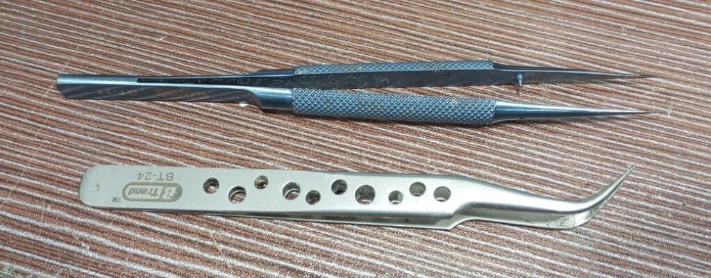
State and Bend Tweezers & Fine Brushes
For handling solder balls, cleaning pads, and positioning the stencil with precision. Bend tweezer is good and very comfortable tools for holding a stencil when reballing IC
🧪 Materials Required
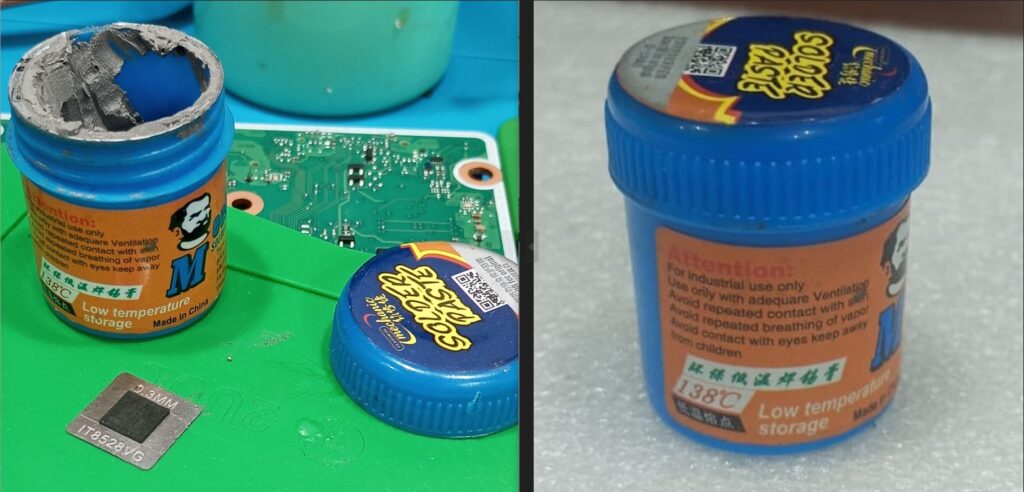
Solder Balls or Low Temperature Alloy Solder Paste
Correct diameter balls are essential for proper connectivity. You can use alloy solder paste. It’s easy and universal.
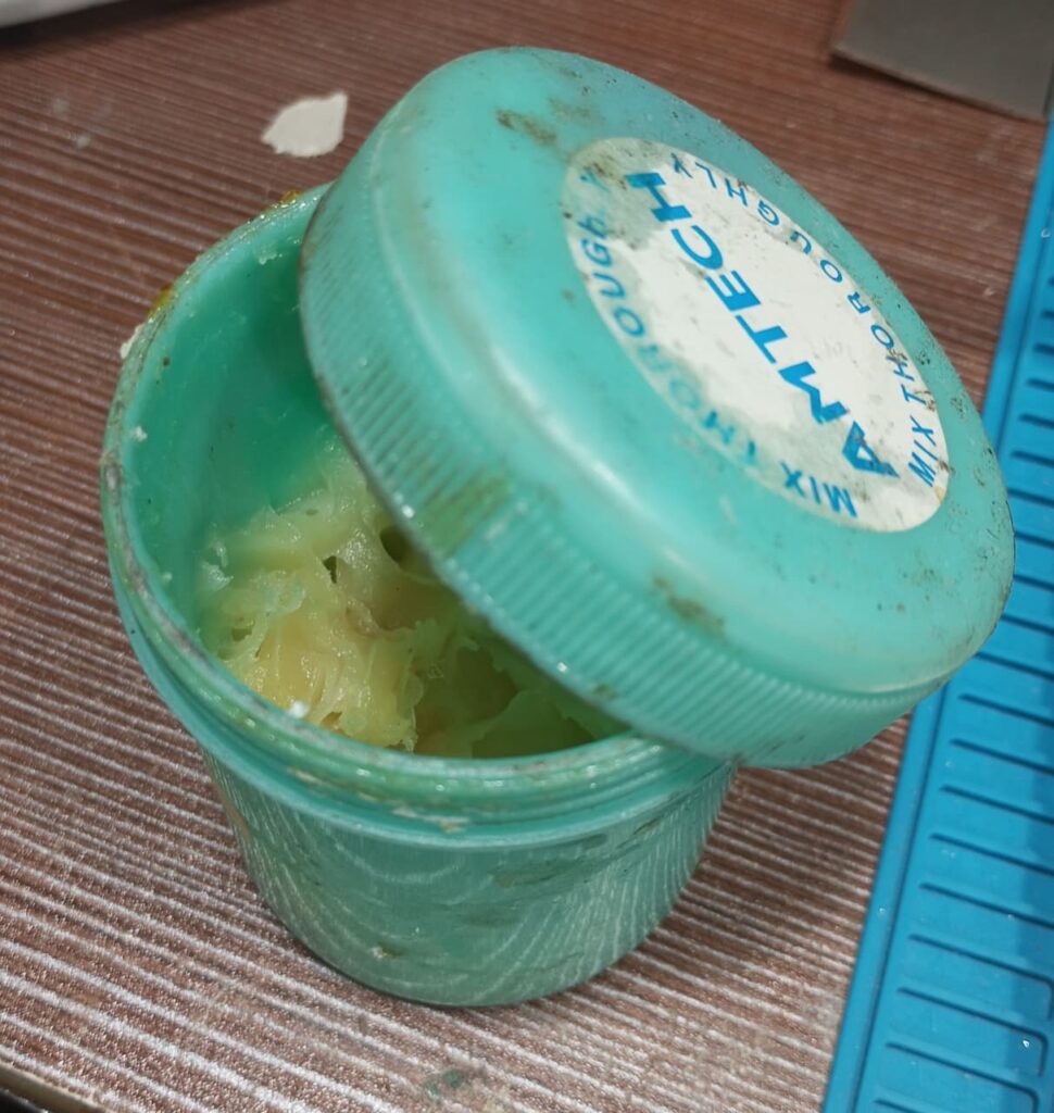
Soldering & Flux (No-Clean or Rosin-Based)
Promotes adhesion, prevents oxidation, and ensures smooth solder flow during heating. Desoldering Flux needed as figure 6:
Isopropyl Alcohol (IPA)
Used for cleaning chip pads and removing flux residues after reballing. Chemical liquids needed low conductivity and stability.
Lint-Free Cleaning Pads
For wiping surfaces without leaving fibers that could interfere with soldering. It’s optional; you can also use a toothbrush. It’s better and cheaper.
💡 Pro Tip:
Always verify the ball size and stencil compatibility before starting. Using mismatched materials can cause misalignment, weak joints, or short circuits. Investing in high-quality stencils and flux pays off in both efficiency and reliability.
Expert & experienced (but Unknown due to new types of technology) can start from here
4. Direct Heating Stencil Method Explained
The direct heating stencil method is one of the most efficient and precise techniques for reballing VGA-type I/O chips. Unlike indirect heating, where solder balls are pre-attached and then reflowed, direct heating allows the technician to place solder balls directly into the stencil and apply heat through it. This ensures uniform melting, strong adhesion, and minimal risk of misalignment.
🔄 Step-by-Step Process
Pad Preparation
First, set the air temp to 310 degree Celsious and remove the chip from the board(360 degrees Celsius for the desktop board). Clean the chip’s contact pads thoroughly using isopropyl alcohol (board cleaning liquid) and a lint-free pad. And Toothbrush is easy to use, better, and cheaper also.
💡 Pro Tip:
Never start heating directly over the IC. Begin by warming the nearby board surface — this helps stabilize thermal flow and protects the IC from sudden stress. It’s a smart move for long-term chip health. Remove any residual solder or oxidation to ensure a smooth surface.
Stencil Alignment
Place the direct heating stencil over the chip, ensuring perfect alignment with the pad grid. Secure the stencil to prevent shifting during heating.
💡 Pro Tip:
If you don’t have a stencil‑alignment padlock for this model and the IC keeps shifting during alignment, here’s the most effective method. After removing the chip from the board, align the stencil before cleaning the old balls.
Once the stencil is perfectly aligned, mark the IC’s edges using a surgical knife according to the chip’s surface reference, just like in Figure 7. This gives you a precise guide and makes reballing far easier and more accurate.
Flux Application
Apply a thin, even layer of flux across the pads. Flux helps solder balls adhere properly and prevents oxidation during heating.
Ball Placement
Drop solder balls into the stencil holes using tweezers or a ball feeder, or fill up the alloy solder paste smoothly. Bend tweezer is best for holding IC. Gently tap the stencil to ensure each hole is filled correctly.
Direct Heating
Use a hot air rework station with controlled airflow (minimum low flow) and temperature (250). Start heating directly from the site of the stencil and slowly move to the center of the IC until the solder balls melt and bond with the pads. Maintain consistent heat to avoid overheating or incomplete bonding.
Cooling & Stencil Removal
Allow the chip to cool naturally for a few seconds. Carefully lift the stencil to reveal the newly formed solder ball grid. Allow the chip to cool naturally for a few seconds. Carefully lift the stencil to reveal the newly formed solder ball grid.
💡 Pro Tip:
Apply desoldering flux and heat one more time if the IC is not removed from the stencil
Inspection
Examine the reballing under a microscope or Magnifier glass to check for uniformity and proper adhesion.
💡 Pro Tip:
After remove chip u can heat once more to align the ball grid. If the 1/2 ball didn’t solder to the IC, you can find the exact hole of the stencil. Rework any misaligned or missing balls before reinstalling the chip.
⚡ Advantages of Direct Heating
- Faster process compared to indirect methods.
- Reduced risk of ball misalignment.
- Stronger and more reliable solder joints.
- Ideal for fine-pitch VGA-type I/O chips where precision is critical.
If this blog or article has helped you in any way and made you feel happy, you’re welcome to support me with a donation. Your support motivates me to continue helping others.
If you are Nepali +9779818674496
Pingback: HP 440 G10/ 450 G10 No Power Problem Solved - wrongchipcraft.com